Power Supply Converter
Introduction
During my second year in the Computer Engineering Technology program, I had the opportunity to work on a hands-on hardware project—a power supply converter. This project involved assembling a circuit that converts AC input into multiple DC outputs. In this blog, I will walk you through the key aspects of this project, including the components used, the assembly process, and the final demonstration.
Understanding the Project
The goal of this project was to take an AC power source and convert it into stable DC outputs of different voltages. We were provided with the necessary components, an enclosure, a schematic diagram, and a list of instructions. The most crucial part was understanding the schematic and ensuring all components were assembled correctly to achieve a functional power supply.
Components and Assembly
Before starting the assembly, I carefully examined the list of components and their placements as per the schematic. Some key steps in the assembly process included:
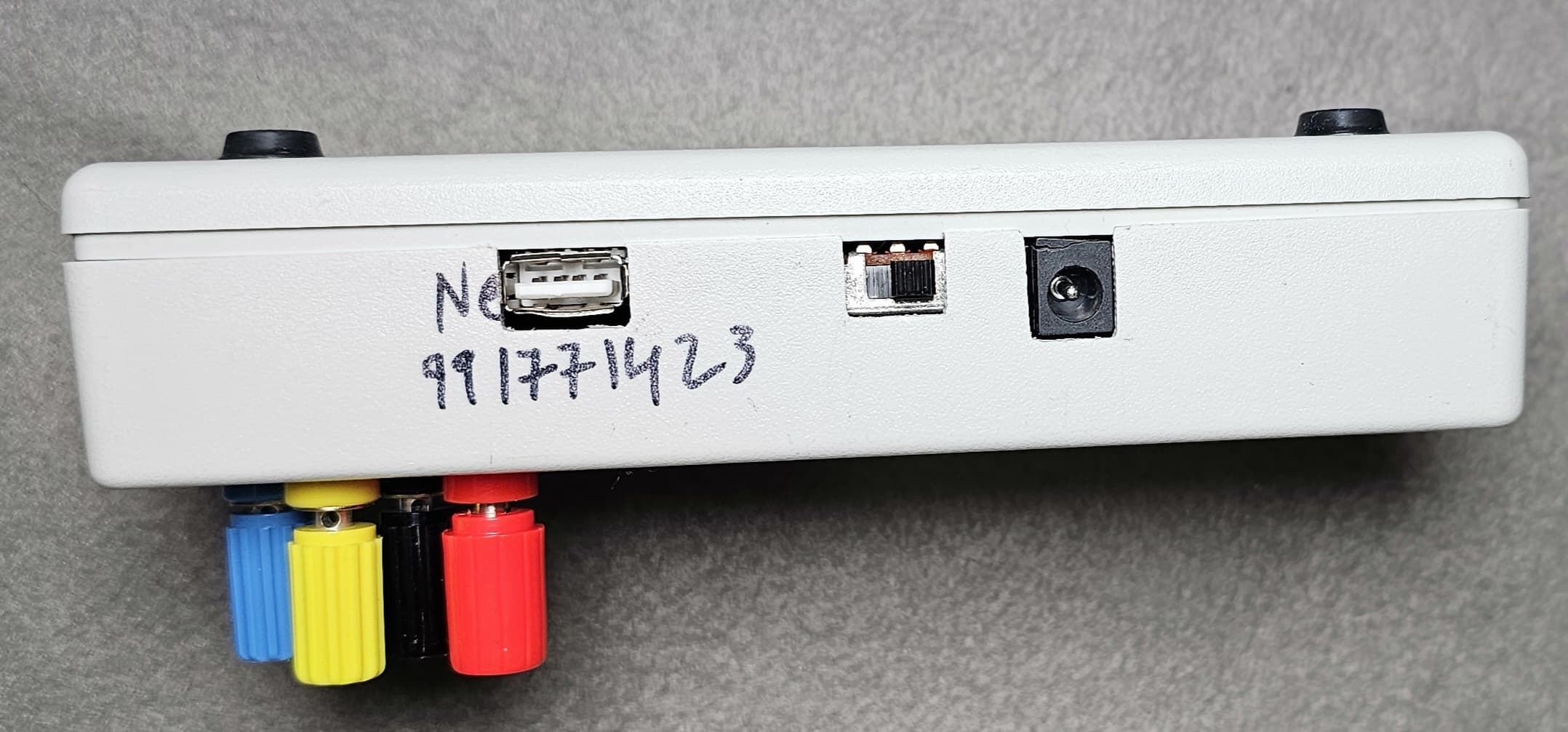
Drilling holes in the enclosure: Measurements were provided to ensure precise placement of the components inside the enclosure.
Following the schematic: This involved placing and soldering each component in the right position to ensure proper connectivity.
Ensuring correct polarity: One of the critical aspects of assembling a power supply is to avoid incorrect connections between positive and negative terminals, which could lead to circuit failure.
Output Voltages
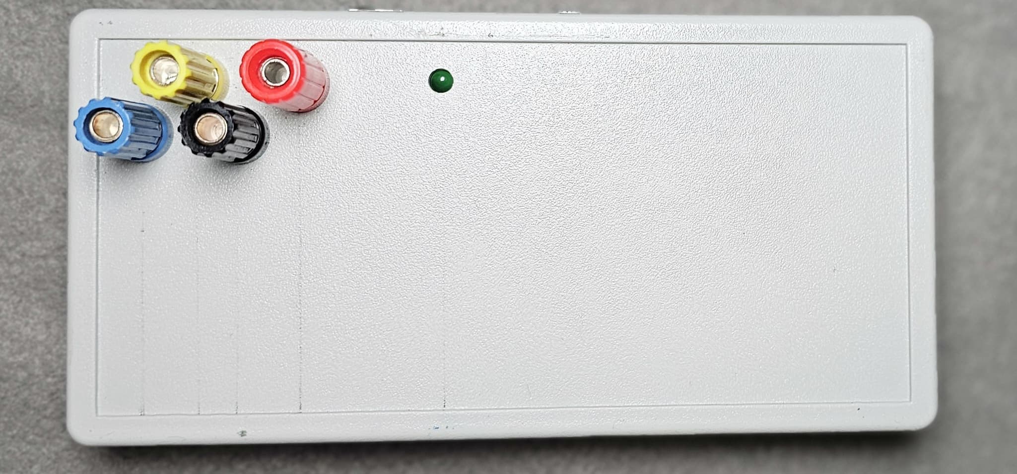
After successfully assembling the circuit, I tested the output voltages. The power supply provided the following DC outputs:
+5V DC (Red wire)
Ground (Black wire)
-12V DC (Blue wire)
+12V DC (Yellow wire)
Demonstration and Testing
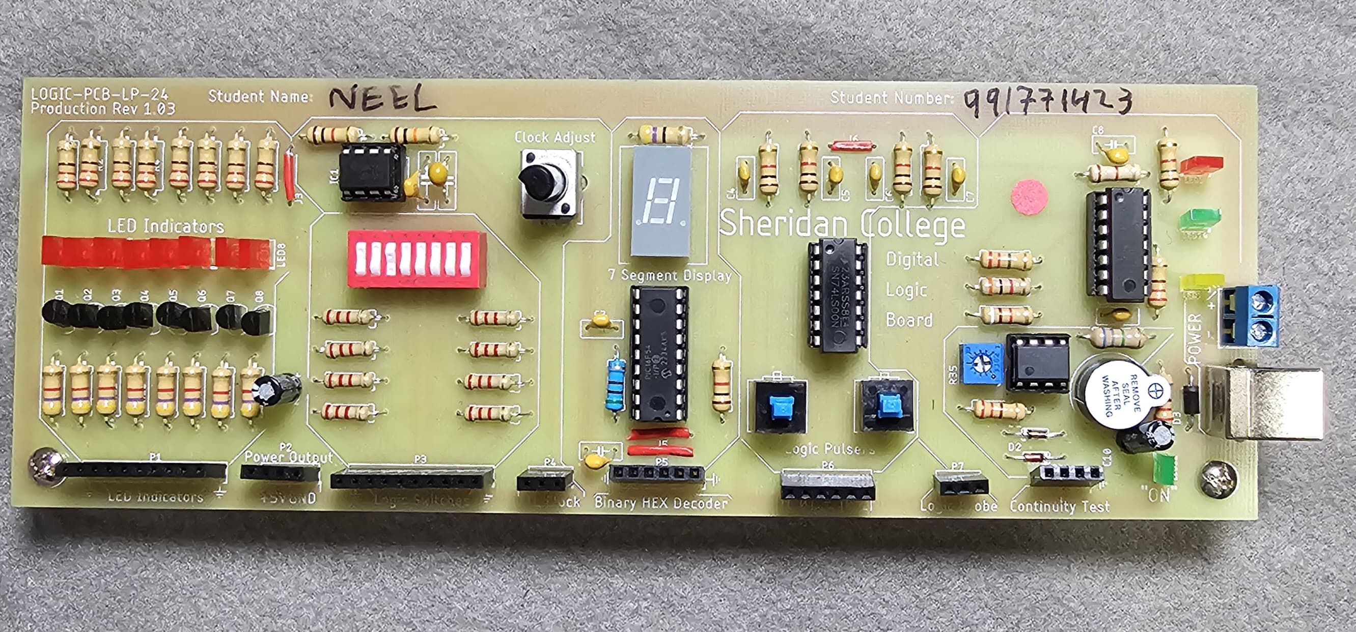
To verify the functionality of the power supply, I connected it to an AC source and checked whether the DC outputs were as expected. For testing purposes, I integrated an OR gate circuit on a logic PCB and powered it using the +5V DC supply.
The test involved setting different input conditions to the OR gate and observing the output behavior:
When both inputs were 0, the output was OFF, as expected.
When either input was 1, the output turned ON, demonstrating correct OR gate functionality.
This successful test confirmed that the power supply was functioning correctly and providing stable DC power.
Media
Conclusion
This project was an invaluable experience in understanding circuit design, schematic reading, and hardware assembly. By carefully following the schematic and ensuring proper connections, I was able to build a fully functional power supply. Such hands-on projects are essential for reinforcing theoretical concepts and gaining practical skills in electronics.